Wan I/O RP2-1204M User Guide
Overview
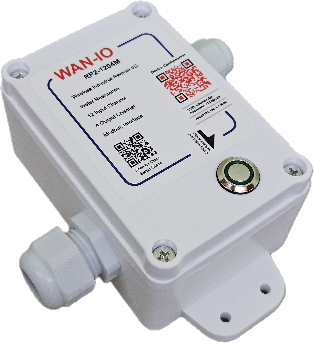
This remote I/O consist of 12 Channel of Opto-isolated input port and 4 Channel of Relay output port.
It is Wi-Fi enable that support various connection security which include, Wi-Fi personal and Wi-Fi Enterprise.
Network Configuration is done through Web brower during Device Configuration Mode.
When it is power up, it will automatically connected to a user configured MQTT Broker/Server. The messaging format is based on JSON string which provide an easy intergration with customer existing system.
At the same time, the device also equiped with the Modbus Slave Interface. The device I/O status and configuration can be done through the Modbus Slave Interface
For more information, please refer to the device specification
Input Port
Total input port is 12 Channel. All the input port is through the bidirectional opto-isolated.
User can either connect based on common positive or common negetive.
The input port are divided into 3 groups. Each group will have their own common input thus provide 3 different set of input type.
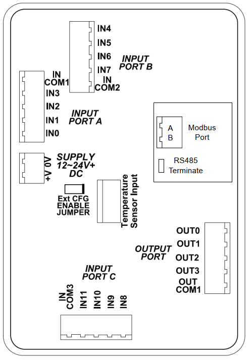
Output Port
Total output port is 4 Channel. All the output port is through relay contact.
The maximum current for each contact is AC230V 5A for non-inductive load. The Total maximum current for all the 4 port is 5A.

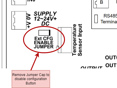
Configuration Button
The control board included with a configuration push button switch. Once press, the device will go into configuration mode and allow the user to use the Web brower to change the device setting. During configuration mode, the indicator will show “Double blink”.
The configuration button can be disabled by removing the jumper cap as indicate in the diagrame below.
RS485/ModBus Bus End Termination
According to the RS485 Specification, the last unit device that connected to the RS485 communication bus required to be terminated.
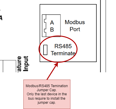
The device can terminate the bus by placing the jumper cap on the “RS485 Terminate”.
Please take node that only 2 RS485 terminate is allowed on each RS485 bus, one is on the Modbus Master unit and the other one is on the last unit of the Modbus Slave unit.
For more information on RS485 cabling and termination, please refer to Guidelines for Proper Wiring of an RS-485 (TIA/EIA-485-A) Network